Antenna radiation efficiency

AnTune is able to measure antenna radiation efficiency at lab bench with just as good result as many other methods.

It is an unique properity of AnTune, not found anywhere else.
As it is an unique method do it need some instructions and understanding if you want to perform such measurements with good result.


If you only need to find out how to open this feature in AnTune, click here to jump to last section at this page.

Measuring antenna efficiency do normally require a dedicated antenna measurement range or anechoic chamber or multi mode reverberation chamber. Such measurements takes time, typical 5 minutes to 1 hour.
In best case will an automatic system deliver antenna-efficiency for a few frequencies, or is it a lot of Excel data to calculate.
An antenna measurement range can be expensive and require a lot of space.
It is in any case a slow method to be waiting until antenna almost is in final design to find out that it beahaves more like a 50 Ohm resistor then an effective antenna. It is not time effective antenna design to find out such problems in finale stages of a project.
It is during antenna design and antenna tuning which it can be of very high value to constantly monitoring how antenna perform from efficiency perspective, but that have so far not been possible, measuring antenna efficiency "live" at lab bench, with no calculations needed or any delays. AnTune will update curve several times per second.
AnTune have removed previous limitations by implementing an unique measurement method described on this page. It makes it possible to measure antenna efficiency over wide frequency range at lab-bench.


AnTune method is based on Wheeler Cap

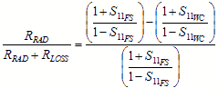
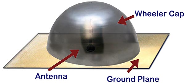
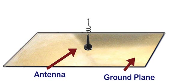
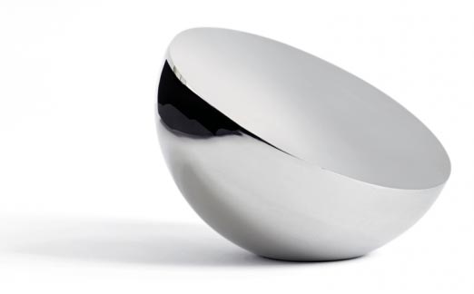
A simple and fast method to measure antenna efficiency was developed by H. A. Wheeler. It was presented 1959 in his paper "The Radiansphere around a Small Antenna".
A metallic cap, a half sphere, completely covering antenna, is the only needed tool, except for a VNA. Cap is placed over an antenna located at a flat ground plane. This makes it possible to measure antenna internal loses (under certain circumstances).
Same measurement, but now with cap removed, will measure internal losses and radiation losses. From these two measurements can then antenna efficiency be calculated.
Basic idea is that an antenna, when at resonance, as it is in resonance are there no reactive losses. Antenna is then a pure resistance consisting of radiation resistance, RRad and its internal loss resistance, RLoss.
If antenna is blocked from radiating do only RLoss exist in opposite to antenna in free space where measured resistance is sum of RLoss and RRad

Antenna efficiency under these circumstances is then easily calculated as:


S11WC = S11 for shielded antenna, Wheeler Cap.
S11FS = S11 in Free Space.

By shielding the antenna such that total reflection occur will RRad become 0 Ohm as no radiation will occur, only RLoss will be measured and by comparing with result from resistance measurement in free space can antenna efficiency now be calculated.

Link to external site with more information about Wheeler Cap: Link
Link to Wheeler Cap original document: Link


Original Wheeler Cap Method

Step 1:
Antenna RLoss at resonance is measured with a cap placed over antenna.


Step 2:
Antenna RRadiation+RLoss is measured in free space.


Antenna efficiency can now be calculated at resonance frequency. There are however many error sources due to variation in cap size and shape. Result is not always correct as a cap can cause detuning effects, often downward in frequency.
Value to do this measurement at lab bench is limited due to antenna impedances must be pure resistive (resonance), which seldom is the case when doing antenna tuning and design work.

AnTune improved method
AnTune have eliminated or reduced most of limitations in method Wheeler cap such that it now is a very practical method.
Here described measurement method have so fare shown to be just as good or better then other alternative measurement methods for resulting antenna efficiency. It is an simple and reliable method to perform, high repeatability, few error sources, but as it is an individual setup method done in an uncontrolled lab environment can no guarantees be done.

In real lab life is antenna impedance seldom a pure resistance at any frequency but by taking method Wheeler Cap a step further and use available computing power can good efficiency calculations be done based on complex impedance measurements.

Wheeler Cap method need a shielding enclosure with a size specific relative antenna frequency.
Size of enclosure was originally critical but AnTune tries to characterize any enclosure and compensate for its dimensions within a reasonable range.
Inside this enclosure should be very metallic clean. No paint, not a grain of RF absorbing material. Enclosure do not need to be extremely RF tight for this particular type of measurement, which simplifies lid design.
Do not select too big can for the first measurements. Less then a wave-length in all directions or smaller is to prefer but antenna must be free in all directions, no metallic contact with enclosure internals.
Use your existing shielded enclosures and do practical testing and ideally, compare results using antennas with known efficiency.
Select as regular shape as possible for the enclosure. Wheeler cap was originally a half sphere with DUT placed in center but measurement error is small for most shapes of cans as long as it is a wide band measurement.

Enclosure for measuring a minor embedded antenna can be as simple as a unused tin can for paint or a can for cookies with a well fitting cap. A specific dedicated shielding box is of course even better.
Drill a hole for a coaxial cable or RF connector feed trough and if needed add plastic foam (non RF absorbing) in box to keep antenna stable inside can without touching any metallic walls.


Shape of enclosure should be kept simple to reduce amount frequencies causing standing waves.


Measurements outside of enclosure
Antenna in free space, that is when complete antenna structure is placed in a non reflective or near field absorbing environment.
Such condition is not achievable at lab bench but it is easy to see in AnTun if unwanted reflections are affecting result.
By moving around antenna above lab-bench can it easily be seen in AnTune if there are any reflections causing false readings as impedance then will vary a lot in narrow frequency band. It is in most cases easy to find a place with less reflections by moving and rotate antenna around lab bench.
Ferrite tubes are in most cases a good help to absorb reflections along coaxial cable so that it not add to antenna proprieties.
When antenna is placed inside enclosure must ferrite tubes remain at outside as total reflection inside enclosure else not will happen.

AnTune method - Procedure and points

  • Start a new antenna efficiency measurement by making a shortcut at antenna base and set port forwarding in AnTune such that a well defined dot 9 o'clock can be seen in Smith Chart.
    That eliminate coaxial cable and less perfect calibration losses to be included in antenna efficiency measurement.

  • Place antenna in a shielded box and save result by pushing [save] button in AnTune.

  • When antenna is removed from box, hold it in free space and antenna efficiency is shown in AnTune.

  • Do not adjust or replace coaxial cable length between these both measurements as even smaller impedance and resistive variations can affect result.
    Is for example a dual SMA used as a feed thrue into an enclosure, replace it with a similar feed thrue when antenna is in free space to keep length and losses unchanged.

  • Use ferrite tubes if possible, but never inside shielded box.

Features that can be unlocked

  • Efficiency
  • Average gain
  • Accepted power
These functions can be unlocked, making it possible to do these kinds of measurements in AnTune. For opening these function must a keyword be entered in AnTune in a way shown in video below.

By entering this keyword in AnTune do you agree to that you have read content in this page and understand that this measurement method can fail if no ideal free space is found above your lab bench, lacking of infinite ground or that your enclosure have unexpected losses such that a forgotten RF absorbing cookie remains in the can.

Link to video at Youtube.

For more information and assistance, please contact us at e-mail address: info@antune.net.


All rights reserved - AnTune 2019